 |
ARDUINO CONTROLLER | |
About a year ago I had a discussion with my friend Gary Swartz about creating a Home Automation System Not a plug and play system purchased from a store, but a personalized system built from the ground up.
Over the months that followed I built a custom system that automates the house lighting and a few other electrical appliances.
In addition to this, my Home Automation application has the ability to receive and respond to voice commands in real time.
I called her Emma-Jane and she controls the lighting and television,
as well as other additional Apps built into her program.
Building a program that has the ability to listen to spoken instructions, respond to them verbally and carry them out in the real world has been a lot of fun and frustration.
Now after using the system for many months, I have decided to rebuild the entire software project from the ground up.
This in order to make improvements on lessons learnt as well as develop a more thorough illusion of intelligence in my home assistant.
But this page is not about the voice control. It is about the underlying hardware that allows the software to interact with the real world.
In order for the software to interact with the real world outside of the PC, I needed an interface that has the ability to control inputs and outputs driven by the PC. Thereby giving the software eyes and hands in the real world.
Options for this kind of control have been both scarce and expensive.
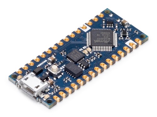
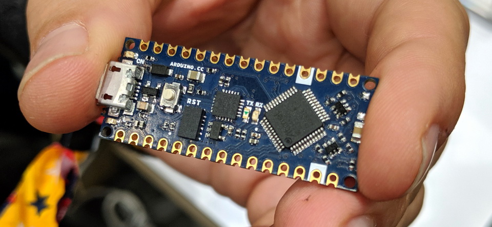
I searched for a suitable controller and found it in the Arduino Micro Controller.
 |
Arduino is an Italian based company that produce and support these controllers.
They are used around the world by makers and project builders like myself.
They are possibly the most popular and most used Micro Controllers in the Electronic Enthusiast
Community.
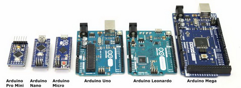
For those unfamiliar with the Arduino family of microcontrollers, there are many variations.
My choice of model was the "Arduino Every". It is a new rendition of their very popular Nano Controllers.
The software described below will however work just as well on the Uno and Nano boards.
 |
These boards are typically used as Stand-Alone controllers.
This meaning that they are small PLCs - Programmable Logic Controllers - capable of running complex code and making decisions independently .
I however intended to use them in a very different manner.
I wanted them to operate as my interface between the virtual and real worlds.
It will sense its environment and pass this information on to the PC.
The software running on the PC will make the relevant
calculations and decisions and pass the output instructions back to the Arduino in order to interact with the real world.
|
OFFERING CONTROL | |
The purpose of this post is to offer my software to fellow makers and enthusiasts who require a means of allowing their software to interact with the real world.
The software is divided into two parts.
The Arduino - which uses a variation of the "C" programing language.
The PC - whose software is written in Visual Basic.
This software is not suited for someone who is looking for a plug and play solution.
This is intended for Makers and DIY Enthusiasts who will plug this software into their own projects.
The Arduino C code does not require any interaction other than changing the Station Address.
- int ArduinoAddress = 0;
The Visual Basic Software does however require a reasonable familiarity with the language and the ability to write code.
I wrote this software as a standalone piece of code that can be easily plugged into other projects in order to add real world interaction to any VB project.
It has the ability to interface with 10 Arduinos simultaneously.
The only interaction with the App that it is being added to, is the exchange of a 15 digit text string.
This makes it really simple to interface with any other application built in VB.
Following below will be a description of the operation of the code.
Below will be the complete C and VB code
available for download in text format.
|
GUI OVERVIEW | |
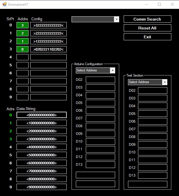 |
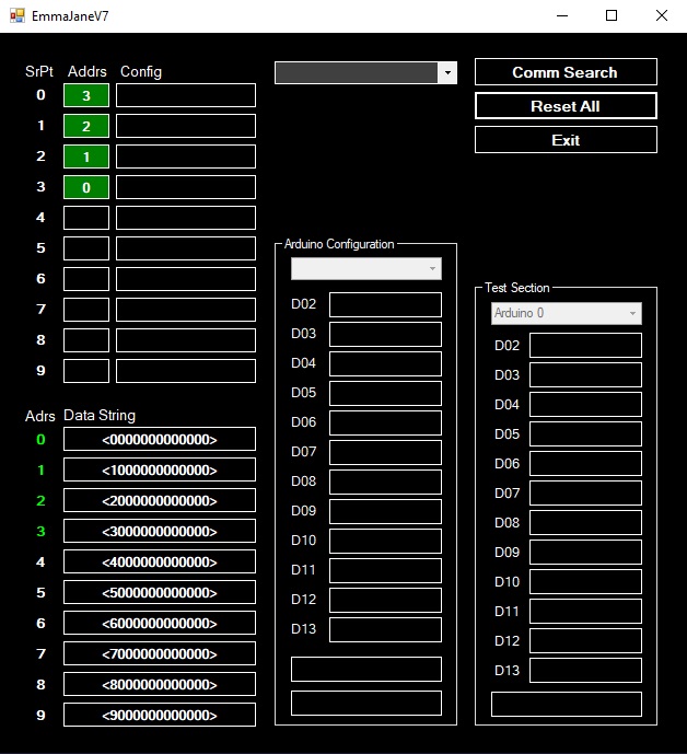
This is the GUI. Very stark and functional yes, but it is intended to run in the background.
On the top left we see the 10 available Serial Ports - SrPt
Next to that is the Station Address of the Arduino that is attached to that Serial Port
The Arduino Address is set in the Arduino C Code
Next to that is the Configuration String
This string tells the Arduino which of its Pins will be used as Outputs and which as Inputs (High or Low)
The table below offers some information as to the meaning of the Configuration String
'[>] Opens String
'[0] = Station Address Number 0 - 9
'[1] = Din02 State - IO - 0,1,2 - 0=InputNL - 1=InputNH - 2=Output - >021122002212<
'[2] = Din03 State - IO - 0,1,2 - 0=InputNL - 1=InputNH - 2=Output
'[3] = Din04 State - IO - 0,1,2 - 0=InputNL - 1=InputNH - 2=Output
'[4] = Din05 State - IO - 0,1,2 - 0=InputNL - 1=InputNH - 2=Output
'[5] = Din06 State - IO - 0,1,2 - 0=InputNL - 1=InputNH - 2=Output
'[6] = Din07 State - IO - 0,1,2 - 0=InputNL - 1=InputNH - 2=Output
'[7] = Din08 State - IO - 0,1,2 - 0=InputNL - 1=InputNH - 2=Output
'[8] = Din09 State - IO - 0,1,2 - 0=InputNL - 1=InputNH - 2=Output
'[9] = Din10 State - IO - 0,1,2 - 0=InputNL - 1=InputNH - 2=Output
'[10] = Din11 State - IO - 0,1,2 - 0=InputNL - 1=InputNH - 2=Output
'[11] = Din12 State - IO - 0,1,2 - 0=InputNL - 1=InputNH - 2=Output
'[<] Closes String
Below is the Data String
This is the real time communications between the PC and the Arduino
It starts with the address and then marks each IO with a 1 for on or a 0 for off
The table below offers some information as to the meaning of the Configuration String
'[<] Opens String
'[0] = Station Address (0-9) - <00100101100000>
'[1] = Din02 - Digit 1 (IO)
'[2] = Din03 - Digit 1 (IO)
'[3] = Din04 - Digit 1 (IO)
'[4] = Din05 - Digit 1 (IO)
'[5] = Din06 - Digit 1 (IO)
'[6] = Din07 - Digit 1 (IO)
'[7] = Din08 - Digit 1 (IO)
'[8] = Din09 - Digit 1 (IO)
'[9] = Din10 - Digit 1 (IO)
'[10] = Din11 - Digit 1 (IO)
'[11] = Din12 - Digit 1 (IO)
'[12] = Din13 - Digit 1 (IO)
'[>] Closes String
In the middle of the Form we see the Configuration section.
This allows the user to configure which Pins will be Outputs and which will be Inputs.
The new Configuration String is then written to the Arduino as well as a text file on the PC
Lastly, on the right of the Form we see the Test Section.
This allows the User to manually change or view any Output or Input on the Arduino.
This is used for testing and trouble shooting
|
BOOT SEQUENCE | |
Let's take a look at the sequence of events that takes place when the software loads
With the Arduinos attached to the USB Ports of the PC, the software is launched.
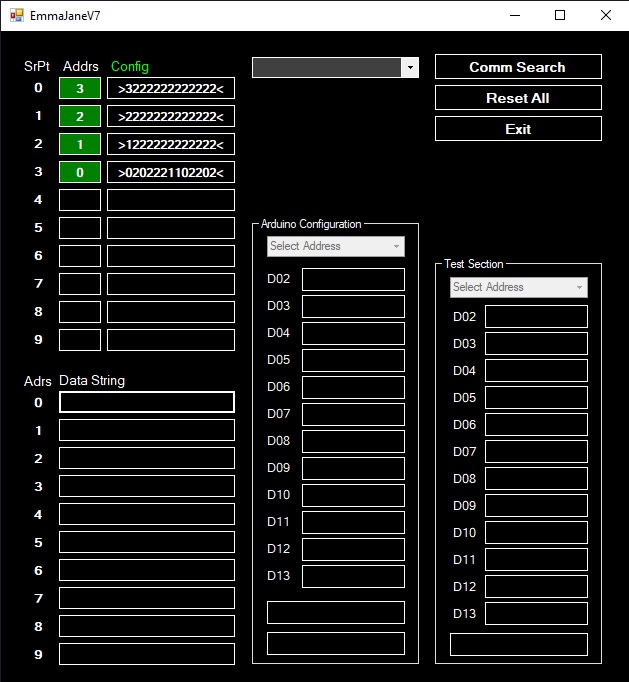
The first thing that happens is the software searches for any attached Arduinos - as below
 |
The Configuration String Text Boxes will indicate >Q0< as below.
This is the Arduino offering its Station Address to the VB Software
 |
The Configuration String for each Station Address is then sent to the Arduino.
The Arduino uses this String to configure its Pins as Inputs or Outputs
Once the Config String is accepted by the Arduino, the unit becomes ready to operate
 |
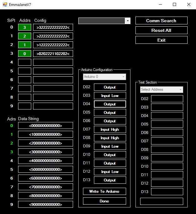
On the left we see the Data Strings ready to convey information between the Arduino and the PC.
In the middle we see the Configuration Section.
This section allows the user to configure the Pins as Inputs or Outputs
0 = Output
1 = Input - Normally Low
2 = Input - Normally High
Once the user has selected the use of each Pin, the Write To Arduino button is pressed to send the new Config String to the Arduino
A copy is also saved to the PC's Drive
 |
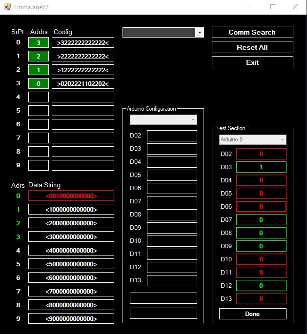
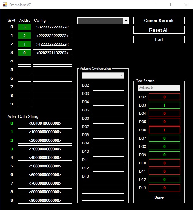
On the right we see the Test Section
This allows the User to select an Arduino by its address and manually controls its Inputs and Outputs
Inputs are marked Green while Outputs are marked Red
In the picture below we see that the Arduino has changed its InputD03 to High - Indicated by a 1
At the same time we see the Data String turn Red to indicate that it is communicating this change between the devices.
The Data String now indicates the value of 1 in its String
 |
Now the User has selected to change Output number 6
D06 has changed to a 1 and the Data String has changed to Red to indicate that it is communicating the change.
The value of 1 for that Output is now visible in the Data String
 |
Once the communication of the Data String is complete, The Data String Text Box becomes White again
This indicates that all devices agree on the state of the string
 |
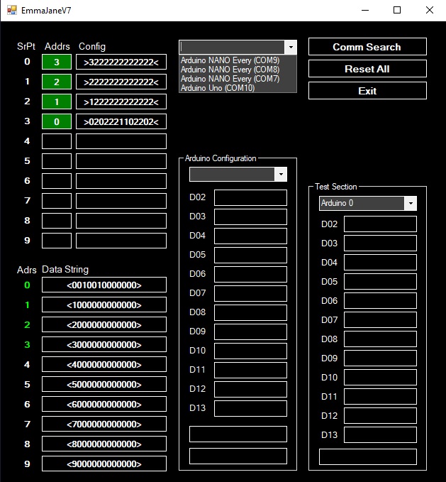
As a means of trouble shooting the USB connectivity, the top center of the form offers a drop down box which lists all the USB devices recognized by Windows that has the word Arduino in its description
 |
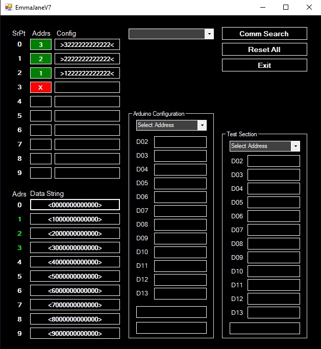
Lastly, there is a Communications Failure routine built into the VB Software
Should an Arduino become unresponsive, VB will try to recover it.
If it fails to recover the unit after 5 attempts, it will mark it as a Comms Fail as seen below.
 |
This concludes the boot sequence from the Users perspective
More information is to be found in the Text Files below.
|
INSERTING INTO SOFTWARE | |
When this code is inserted into a VB Project, it acts independently to the other code.
The only interaction between this code and that to which it is being added, is the Data String.
The Programmer simply reads the Inputs from this string or modifies it by changing a 0 to a 1 in order to switch an Output on.
Simple and tidy.
|
THE SOFTWARE | |
In the interest of Open Source mentality, I make this code available to anyone to use or distribute as a whole or as parts thereof - provided it is not for commercial use.
Below are the complete text files containing firstly the Arduino C Code and secondly the Visual Basic PC code.
ARDUINO "C" CODE
ARDUINO "VB" CODE